
AICV(Autonomous Inflow Control Valve)
AICV TECHNOLOGY FUNDAMENTALS
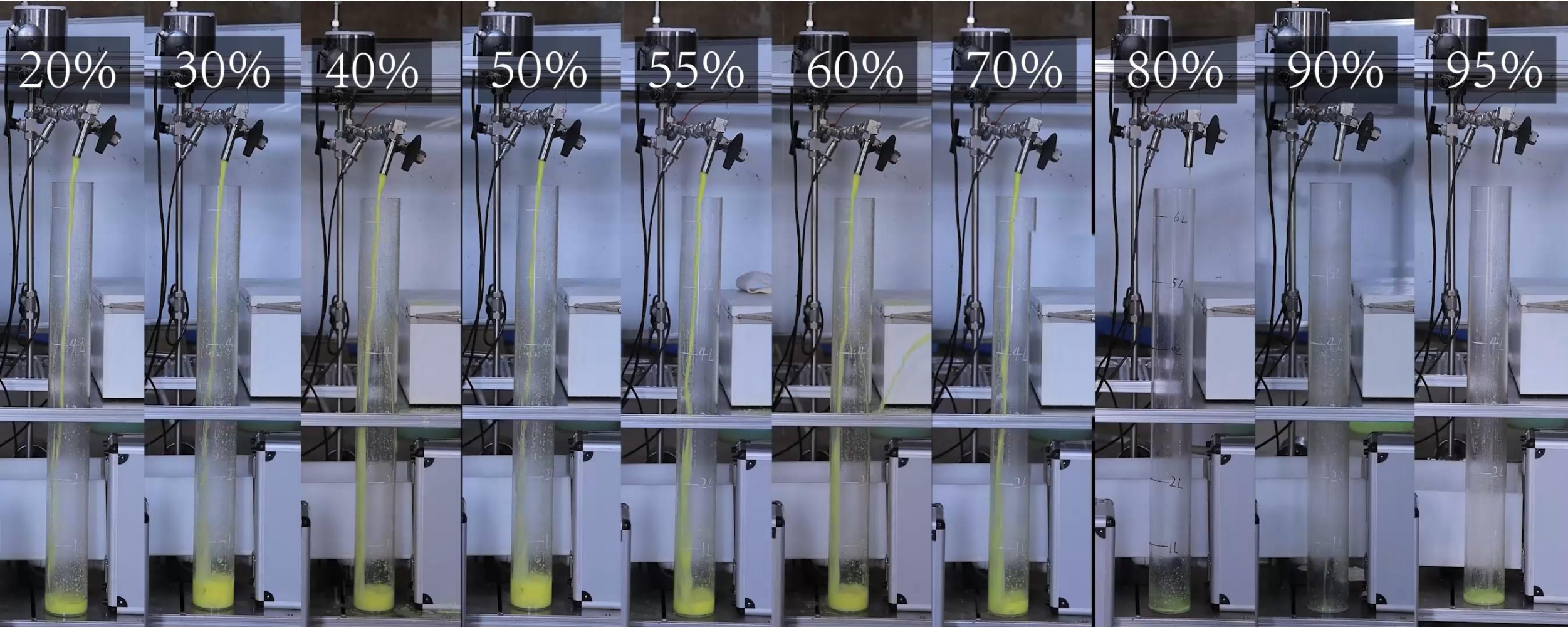
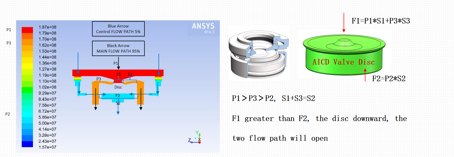
Flow Simulation Analysis (Oil Medium):When oil (high-viscosity fluid) passes through the valve, it experiences significant pressure loss downstream. This results in insufficient upward force on the valve plate, causing the entire valve assembly to move downward. Consequently, both the main flow path and control flow path open.
Flow Simulation Analysis (Water Medium):When water (low-viscosity fluid) passes through the valve, it exhibits minimal pressure loss downstream. This generates sufficient upward force on the valve disc, causing the valve disc to move upward. Consequently, the main flow path closes while the control path remains open.
The “Smart Traffic Cop” for Down hole Fluids
1. Key Misconception: AICV is NOT an Oil-Water Separator
In many customer discussions, the most common misunderstanding is that an AICV acts like a filter-type oil-water separator, which lets oil flow through while blocking water at the bottom of the well. This is not true.
Separators use physical blocking:
Real separators rely on physical barriers (screens, baffles) to block fluids. However, under high downhole pressure, oil and water molecules are nearly identical in size. No physical screen can block water while only allowing oil to pass.
AICV uses intelligent recognition:
The AICV is essentially an autonomous flow-restriction device. It does not physically separate oil and water at the molecular level. Instead, it acts like a smart gatekeeper that identifies fluids by their “character” — viscosity.
- Its role:
It does not block water. It recognizes water and instantly reduces the flow area /flow path for water, so water production drops sharply.
- Final result:
Water is not eliminated, but its production is greatly suppressed, leaving valuable flow channels for high-value crude oil.
2. Technological Gap: AICV vs. Conventional ICD
Conventional ICDs (fixed-nozzle Inflow Control Devices) have been widely used for over a decade, but there is a clear generational technological difference between ICDs and AICVs.
- Conventional ICD = “blind”:
It has only a fixed flow path and cannot tell oil from water. It allows inflow /produce as long as there is pressure, without caring whether it is oil or water that is being produced.
The nozzle size must be pre-designed using NETool software. If the simulation is wrong or downhole conditions change, the ICD becomes ineffective.
- Our AICV = “intelligent and responsive”:
It uses a secondary channel for real-time sensing.
When water content increases, it automatically closes the main flow path.
When oil content increases, it automatically opens the main flow path.
It does not require pre-calculated nozzle sizes — it makes autonomous decisions based on actual downhole fluid conditions.
| Features | Conventional ICD (Fixed Nozzle) | Smart AICV (Autonomous Valve) |
|---|---|---|
| Working Mode | Manual / Fixed Size | Automatic / Self-Regulating |
| Design Logic | Pre-designed by software; fixed after installation | Real-time physical sensing; auto-adjusts downhole |
| Fault Tolerance | Fails if actual conditions differ from simulation | It can self-heal. Even if the geological parameters are inaccurate, it can adjust according to the actual fluid dynamics. |
| When Water Breaks Through | Balances flow only; cannot shut off water | Breakthrough flow control: Once water enters a certain section, the AICV can be reduced to 1/20 of the original level. |
In simple terms:
An ICD is like a fixed hole in a pipe — it cannot tell what fluid is passing through.
An AICV is a smart sensor valve: fully open for oil, nearly closed for water.
3. How AICV Works: The “Viscosity-Sensing” Technology
The AICV’s intelligent control comes from a sophisticated main-and-secondary channel physical sensing system.
- Secondary channel = sensor / brain: identifies oil or water.
- Main channel = actuator / gate: controls production rate.
- Actuating force = friction resistance:
Thick oil creates high resistance and opens the gate;
Thin water creates low resistance and closes the gate.
The system is fully mechanical, with no electricity or hydraulic lines — extremely reliable.
1. Recognition Mechanism: Viscosity = “ID Pass”
The AICV judges fluids by flow resistance, not by sight.
Two critical viscosity thresholds:
- Oil (viscosity > 0.815 cP):
Crude oil is viscous. When it flows through the secondary channel, it creates high friction, which acts as a force to fully open the main flow path.
→ Valve fully open: 100% oil production.
- Water (viscosity < 0.621 cP):
Water is thin and creates very low friction. Without enough force to open the gate, the main flow path automatically closes.
→ Production restricted: only the secondary channel is open, at 1/20 of full rate.
2. Powerful Water Control: 1/20 Flow Restriction
Once the AICV detects water (viscosity < 0.621 cP), it imposes extreme flow restriction:
- Restriction ratio:
Water production is limited to 1/20 (5%) of normal oil production.
- Economic benefit:
Even if water breaks through in a zone, the AICV immediately cuts 95% of unwanted water production.
This maximizes pump efficiency for crude oil only.
Summary
The AICV is the downhole “automatic flow-limiting switch.”
It does not separate oil and water — it recognizes viscosity.
- High viscosity (oil): gate fully open.
- Low viscosity (water): gate nearly closed.
It reserves production channels for oil and locks water out.
AICV Fluid Identification & Production Control Table
| Fluid Type | Viscosity (cP) | AICV Identification | Valve Status | Production Rate |
|---|---|---|---|---|
| High-Viscosity Fluid | > 0.815 | Crude Oil | Full Open | 100% |
| Mixture | 0.621 – 0.815 | Mixed Fluid | Auto-Regulate | Dynamic Balance |
| Low-Viscosity Fluid | < 0.621 | Formation Water | Restricted | 5% (1/20) |